SPM12 Revised Normalization
Goal: Warp a native space anatomical image into standard MNI space. As established by the lesion normalization experiments, SPM12 does a nice job of normalizing the head, even the lesioned head, without a lesion mask. It is beneficial to normalize the head before drawing the lesion for the following reasons:
- We can visually inspect the head, insuring that the normalization was good.
- The head will be correctly aligned, with a nice straight midline. This facilitates comparing one hemisphere to the other which is often very helpful in identifying which tissue is abnormal.
- The head’s appearance will be more consistent with all other heads the tracer encounters, which should facilitate consistency (yet to be determined)
- We reduce the total number of steps, because we no longer need to normalize the lesion.
- By reducing the number of steps, we reduce the possibility of interpolation and thus avoid introducing non-binary values into the mask.
- The standard brain mask can be used to prevent auto segmentation of the lesion from leaking outside the brain.
Warning
This normalization first approach works well for homogenous high-resolution (e.g., ~1.0mmx1.0mmx1.0mm) research T1w images. However, the heterogenous datasets that sometimes characterize stroke datasets (CTs, clinical scans) are not necessarily well suited to this approach.
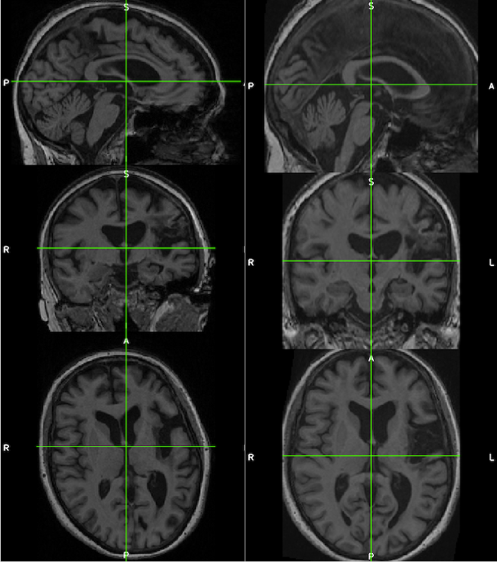
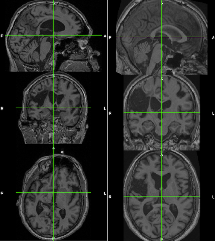
The images below demonstrate the consistency and corrected alignment of the normalized heads (left=native; right=normalized). Data were provided by Liew et al. 2018.
See the suggested lesion drawing approach described in the introduction to ITK-SNAP Segmentation of Stroke-related Lesions.
Data
The anatomical image must not be zipped (i.e., T1w.nii is okay, but T1w.nii.gz is not). Sample data is described, and available for download.
Steps
Segment: Estimate Warp Field
- Open Matlab (and optionally navigate to the relevant directory).
- Type spm at the Matlab command prompt. This will open spm
- Click the fMRI button which will open the windows you need.
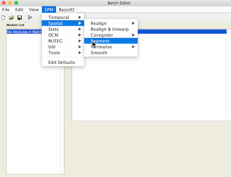
- Select Batch and from the menubar: SPM ➜ Spatial ➜ Segment
- Under Volumes, an X is displayed, indicating that this parameter must be specified. Specify the native space anatomical image (whole head)
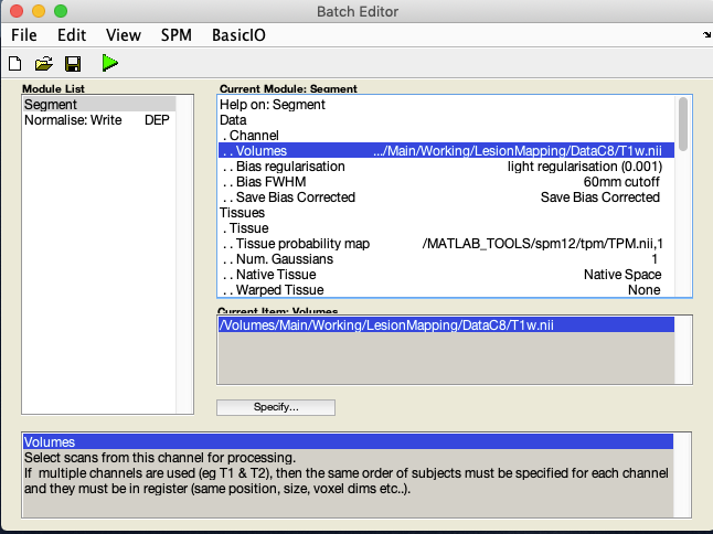
- A few lines below Volumes you will see Save Bias Corrected. By default it is set to Save Nothing. Select it and choose Save Bias Corrected
- Scroll down to the bottom of the module options, and set Deformation Fields to Forward. The Forward warp will be used to warp files from native space into standard space. If you elect to create an Inverse deformation as well, choose Inverse + Forward. That would create an additional warp allowing you to deform files from standard space into native space.
- This is your first batch module. Now we’ll add another.
Normalise: Apply Warp Field to Bias Corrected Head
- From the Batch editor, choose: SPM ➜ Spatial ➜ Normalise ➜ Normalise: Write
- This adds a second module to your batch
- Double click Data. Deformation Field and Image to Write now appear in the menu.
- For Deformation Field, click Dependency and select Segment: Forward Deformation to specify the y file, even though you have yet to create that file. Click OK.
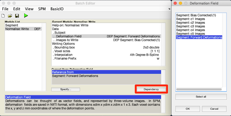
- For Image to Write, click Dependency and select Segment: Bias Corrected (1)
- By choosing to bias-correct we correct for greyscale gradients that could result in misleading tissue intensities across the image.
- Under Voxel sizes enter [1 1 1]
- By choosing [1 1 1] instead of [2 2 2], we are retaining the higher resolution and tissue contrast of the original image. This assumes the original image is higher resolution.
Note
There are 8 1x1x1 voxels in each 2x2x2 voxel, so the resolution difference is considerable.
Run Batch and View Results
- Run the batch module by clicking the green go button (upper left on batch editor).
- Segmentation produces:
- Files prefixed with c for each tissue type and the skull.
- A seg8.mat file containing segmentation parameters.
- A deformation field image with y prepended.
- A bias corrected T1w image with m prepended.
- Normalization produces:
- An anatomical image in standard MNI space, also with a wm prepended.