Working with Clinical Data
Clinical data differs from our typical research MRI data in several ways:
- Voxels are often extremely anisotropic. In clinical scenarios patients may be unable to hold still for the long periods routinely expected for research. Clinicians meet this challenge by collecting multiple short orthogonal scans that have high in-plane resolution but very thick slices.
- Clinical scans are more likely to involve a contrast agent.
- Clinical scans are more likely to be CT instead of MRI (CT is fast, and safe for people with metallic artifacts).
Simple Image Fusion
As noted above, clinical scans are often characterized by separate images in each of the three orthogonal planes. These images have high inplane resolution but extremely thick slices. It is possible to combine these images in a process called fusion. At its most sophisticated, fusion involves the use of clever algorithms that optimize features of interest. Here I describe the fusion process using averaging. This can easily be accomplished in FSL tools. Download and unzip the following data: fusion.zip. cd to the fusion directory to find three images:
T1w_defaced_axial.nii.gz
T1w_defaced_coronal.nii.gz
T1w_defaced_sagittal.nii.gz
Find the smallest inplane voxel size in all three images, and reslice all three of the images to isotropic voxels using this highest resolution value. In the fusion.zip files, that is 0.72mm in T1w_defaced_axial.nii.gz You can use iso.sh described above in the section on correcting anisotropy. Here are the three commands you need to type:
iso.sh T1w_defaced_axial 0.72
iso.sh T1w_defaced_coronal 0.72
iso.sh T1w_defaced_sagittal 0.72
Register all of the high resolution isotropic images together using reslice.sh. First, register the coronal image to the axial image:
reslice.sh T1w_defaced_coronal_0.72mm T1w_defaced_axial_0.72mm
Also register the sagittal image to the axial image (Note these are slow commands to run, you now have very high resolution images to register):
reslice.sh T1w_defaced_sagittal_0.72mm T1w_defaced_axial_0.72mm
Now, average the images together:
fslmaths T1w_defaced_axial_0.72mm.nii.gz -add T1w_defaced_coronal_0.72mm_resliced.nii.gz -add T1w_defaced_sagittal_0.72mm_resliced.nii.gz -div 3 mean_T1w
The above command adds each of the registered images together and then divides the results by 3 to get the mean_T1w.nii.gz image.
CT Scans
Gantry Tilt
One problem encountered in CT images is the elongation of the skull resulting from gantry tilt as in the image on the left below. If you use dcm2niix for conversion from DICOM to NIFTI, an image with gantry tilt correction will be generated automatically (image on the right, below).
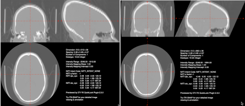
Left Gantry tilt causes elongation of the skull in the nifti file. Right: dcm2niix corrects for the gantry tilt in an image named with the keyword Tilt.
Note
This tilt correction changes the dimensions of the image! See the JPEG Stack Export section for a description of how to reslice your distorted image into undistorted space. It is the last step in producing a good CT nifti image.
CT Windowing (Contrast) Issues
Whatever tool you use for conversion of CT DICOMS (dcm2niix MRIconvert etc.), you are likely to see windowing problems in the NIFTI format. In the picture below, we display the DICOM image on the left and the NIFTI image on the right. Obviously the NIFTI image is not suitable for lesion drawing.
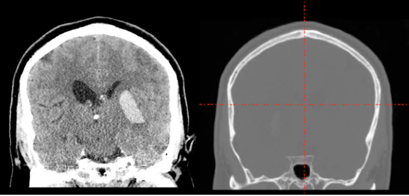
What happened? The CT image contains large negative numbers in the dark area surrounding the head. The bone of the skull is extremely bright. The soft tissue contrasts are small compared to the background and bone values.
There are a couple of partial solutions: A script scaleCT.sh, which I wrote to call FSL utilities to correct the problem; and a solution which is part of the SPM12 Clinical toolbox by Chris Rorden (This toolbox is specifically designed to normalize CT and other clinical scans using lesion weighting. In the process of creating the normalized data, though, it generates a new native space CT with the prefix c. This new image has much better contrast than the original but still is not great for drawing lesions).
However, both of these windowing solutions obscure features of the image which are visible in the original dicoms. If you are willing to spend the time, then the JPEG Stack Export described below preserves the original dicom detail. This requires that you install FIJI and the NifTio plugin for FIJI.
JPEG Stack Export
Tools
Steps when you have DICOMS
- Horos ➜ File ➜ Export (JPG)
- FIJI: File ➜ Import ➜ Image Sequence: point at jpg dir, they are viewable now.
- FIJI: To export properly to NIFTI, you want to orient the image correctly in FIJI. My current experience suggests you want the head to appear upside down in FIJI so that it will be rightside up in NIFTI (this is true for the axial, coronal and sagittal). In addition, for the sagittal image, you want the left hemisphere to appear at the beginning of the stack (that is, when the FIJI slider is on the left).
- FIJI: Image ➜ Transform ➜ Flip Vertically (Yes, all the slices): This should make the image upside down).
- FIJI: Sagittal only: Image ➜ Transform ➜ Flip Z (Yes, all the slices): This should switch the through plane (Left-Right).
- FIJI: File save as Nifti1.
- Create NIFTI from DICOMS: To get the correct labels and dimensions applied to the JPEG stack image, you will need the NIFTI file created by converting DICOMS to NIFTI. Generally dcm2niix is quite nice for this, especially since it detects gantry tilt. However, MRIconvert is less likely to decide that your CT images should be split into several smaller images.
fslcpgeom:
Bad_contrast: The NIFTI file created from the DICOMS should have the correct labels and dimensions, but terrible contrast (this is NOT the gantry tilt corrercted image).
Bad_dimensions: The NIFTI file created from the JPEG stack, has good contrast, but the dimensions are all wrong and labels are missing.
As long as Bad_contrast and Bad_dimensions are in the same orientation (when you view them), you can copy the geometry of Bad_contrast to Bad_dimensions to produce a NIFTI file with good contrast and good dimensions:
fslcpgeom Bad_contrast Bad_dimensions
Do NOT use the gantry tilt corrected image for fslcpgeom.
Check your output: Clinical CTs appear to be very heterogeneous. Make sure the labels on the anatomy are correct (i.e., S [superior] is at the top of the head, A [anterior] is at the front of the head etc.
Ensure your images are in the standard orientation. This will make everything easier. Especially if you are going to apply tilt correction, make sure the tilt corrected image has also undergone fslreorient2std:
fslreorient2std good_image good_image_reoriented
fslreorinet2std tilt_corrected_image tilt_corrected_image_reoriented
Once you have your good_image_reoriented, you still need to apply tilt correction. You can do this with reslice.sh
reslice.sh good_image_reoriented tilt_corrected_image_reoriented
Film ➜ JPEG ➜ NIFTI
Hopefully you’ll never have to do this. It isn’t optimal, but seems to work.
- Look at your film. It should contain information about slice position in mm. From consecutive slices you can calculate slice thickness. In addition, you should have a resolution (e.g. 256 x 256) and FOV (field of view) (e.g., 230 mm). From these items you can determine in-plane voxel size (230/256=0.898). You will need this information later.
- You need digital images of the film. I used an ipad with the white flashlight app as a light table, then took square pictures of each panel in the film. I tried hard to keep everything level and to ensure that each panel filled the square picture frame.
- Even if you do a really good job of keeping each panel straight in your photo, it seems like whoever creates film does not have in mind that someone might do this. That means the various slices you get aren’t properly aligned.
- These pictures may need to be deidentified. I used a photo editing program and blacked out the patient name and institution.
- You may want to resize the images: my originals were 3024x3024. I resized them to 512x512. At 512x512, pixel dimensions will be half my original calculation (e.g., 0.449 mm in-plane).
- As described above, we’ll now use FIJI File ➜ Import ➜ Image Sequence: point at jpg dir. You need to ensure that these images are grayscale. My phone takes color images by default and NIFTI cannot handle that. When you import the image sequence, FIJI gives you the opportunity to Convert to 8 bit Grayscale, which does the trick.
- As previously mentioned the slices are unlikely to be properly aligned.
- FIJI: To see this, choose Image ➜ Scale, and set your voxels to the correct sizes (e.g. 0.449, 0.449 and 6.5 in my case). FIJI generates a second image.
- FIJI: Choose Image ➜ Stacks ➜ Orthogonal Views. My original image was sagittal. On the left, below, you see the uncorrected coronal view. Red arrows point to the locations on the skull that are really out of alignment.
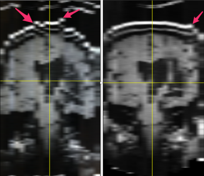
Left: MR images from film: when stacked, the slices do not line up (illustrated by the red arrows pointing to misaligned skull. Right: The alignment of the stacks has been improved using FIJI plugins stackreg and turboreg.
- FIJI has many plugins available. I chose and installed stackreg and its dependency turboreg.
- Using my original unmodified stack (which may or may not be important), I selected the middle slice as the anchor and ran stackreg by selecting it from the plugins menu. I kept the default rigid body registration to avoid any possibility of altering the lesion. The result can be seen in the image above on the right. It is not perfect (see the arrow), but it is considerably improved compared to the image on the left.
- FIJI: flip vertical, flip z. Save as NIFTI1: anat1
fslswapdim anat1 -z -x y anat2put anat1 into the standard orientation, but without anatomical labels. You will have to play with these options.- Unlike the Steps when you have DICOMS, I did not have a NIFTI image for this subject to copy my geometry from. Fortunately, I had an image from another subject with the same dimensions, and this worked well:
fslcpgeom sub-0304_reoriented.nii.gz anat2.nii.gz