Image Processing Tips and Tricks

Maintainer: Dianne Patterson Ph.D. dkp @ email.arizona.edu
Date Created: 2019_08_17
Date Updated: 2019_09_14
Tags: anat, segmentation, image formats, header editing, registration

Most of the tools described below are based on FSL. FSL is not the only tool that can be used for this sort of processing, it is just the tool I know best. Where appropriate, bash scripts are available for download from my Bitbucket tools site. You can just download the whole repository if you want, but it’ll include scripts that may be of no interest. Otherwise, the scripts you want are described in each section (left click a link to view the script, right-click to download). Also, see the Clinical Scans page for issues related to processing data from clinical scans (which may be CTs and or have very low resolution in two of the three planes).

Anatomical Image Preparation

Strutural images, usually T1-weighted, but sometimes T2-weighted, FLAIR, scalar DWIs (B0, FA, MD etc.) or even CTs may be available as underlays to draw lesion masks on. CTs are a really special case and are discussed separately on the Clinical Scans page. T1w images can be processed with a single script described in Prepare T1w Image that reorients, bias-corrects, crops and even generates a brain mask. Several of these processing steps can also be handled separately as described in other sections below.

Prepare T1w Image

For a T1w image, you can use prep_T1w.sh to run fslreorient2std, robustfov, bias correction, and to create a brain mask for a T1w image. Note that prep_T1w.sh depends on FSL and on two additional scripts being present: fsl_anat_alt.sh and optiBET.sh:

prep_T1w.sh sub-001_T1w

Optionally, if you have a lesion mask in native space, you can ensure that it also gets cropped and reoriented by adding it to the prep_T1w.sh command:

prep_T1w.sh sub-001_T1w lesion

Check the brain mask! Large lesions, especially chronic lesions near the surface of the cortex, frequently result in a brain mask that does not have enough coverage. If all of your data consists of high quality research scans, then consider using SPM12 normalization before you delineate the lesion. That way, you can use the standard brain mask instead of generating a brain mask.

Running prep_T1w.sh creates a subdirectory named after your anatomical file, e.g., sub-001_T1w.anat. It also backs up your original files, e.g., sub-001_T1w_orig.nii.gz and optionally your lesion file if you processed it, e.g., lesion_mask_orig.nii.gz. The suffix _orig has been added to these original files. Your new cropped images will have the names that you originally passed in (e.g., sub-001_T1w.nii.gz and lesion_mask.nii.gz).

fslreorient2std

It never hurts to reorient the image to standard orientaion. Some viewer programs will show you the image in standard orientaion whether or not it is stored that way. Other image viewers will show you the image as it is stored. For the sake of consistency, ensure the image is stored in the same orientation as the MNI standard. You can try this test data to see fslreorient2std in action: sub-001_T1w.nii.gz (this is my head, so no worries about HIPPA, it is free to use):

fslreorient2std sub-001_T1w sub-001_T1w_reoriented

The command is harmless if the data is already correctly oriented. If you apply the above command to the ITK-SNAP tutorial data T1w_defaced.nii.gz, nothing changes.

Crop Neck with robustfov

Crop the anatomical images, thus removing the lower head and neck. This command will run fslreoreint2std if it has not already been done.:

robustfov -i sub-001_T1w_reoriented -r sub-001_T1w_cropped

Correct Extreme Anisotropy

Clinical images often have extremely anisotropic voxels. This is not well handled by tools like MRIcron. In addition, ITK-SNAP needs isotropic (or near isotropic) data to do good semi-automated segmentation. You can easily make voxels isotropic with flirt: A simple FSL-based script to facilitate creating isotropic images (anatomical images or masks) is available here.: iso.sh. To try the script out, download T1w_aniso.nii.gz:

iso.sh T1w_aniso 1

The above command takes T1w_aniso.nii.gz as input and reslices it to 1mm isotropic voxels. The output is called T1w_aniso_1mm.nii.gz. The output image can now be used in ITK-SNAP or MRIcron. Note that the image is just as blurry, but it has more slices in the z direction now. That means any mask you draw will be smoother.

Reslice Other Anatomicals into One Space

You can use the script reslice.sh to facilitate running FSL flirt:

reslice.sh anat_FLAIR anat_T1w
  • This example reslices an image, anat_FLAIR.nii.gz to be in the same space as anat_T1w.nii.gz.
  • The script can be used, for example, to ensure that images of several different modalities are in the same space so they can be used with 3D segmentation clustering in ITK-SNAP.
  • Clinical CT Another useful application of reslice.sh is to apply gantry tilt correction (Use the gantry tilt corrected image as the reference image).
  • Fusion Images In the section on fusion images, I walk you through using reslice.sh to create a very simple fusion image.

Warning

reslice.sh uses trilinear interpolation, which is fast and fine for anatomical images. However, it is NOT appropriate for reslicing masks.

Masks

A mask (such as a lesion mask) should be binary, that is, it should contain ONLY 0’s and 1’s. This is because statistical programs for evaluating lesion masks, along with various image math procedures often assume the values are 0’s and 1’s. So, we want to make sure the masks remain binary.

Some tools, like MRIcron, offer a smoothing option for masks. The problem is that smoothing may be accomplished by softening the edges which means that those values are interpolated (i.e., 1’s are replaced with values like 0.5, 0.3 etc). In addition, if you register your mask to a different image space you can introduce interpolated values if you fail to use Nearest Neighbour interpolation. You should go through the Hidden Problems Section below, before registering a mask. In this section, I offer several tools for improving masks without compromising their binary nature.

Ensure Masks are Binary

If you reslice a mask into a different space, you should do so with Nearest Neighbour interpolation. Otherwise, values at the edges of the mask may be interpolated between 1 and 0. Smoothing a mask may result in the same problem. To ensure masks are binary, use fslmaths:

fslmaths lesion -bin lesion -odt char

Check that a mask contains correct values (-M Mean of non-zero voxels should be 1. -S Standard deviation of non-zero voxels should be 0:

fslstats lesion -M -S
1.000000 0.000000

Erode

Remove islands and spikes by eroding the edges of the lesion mask. erode.sh is a bit less complex to call than the fslmaths command. In the command below, we do one iteration of the erosion and do it in 3D (default is 2D):

erode.sh lesion 1 3D

Warning

Be Careful with erosion! If you run too many iterations on a small mask, the mask will disappear! You might want to make a backup copy of your mask first.

Dilate

Fill tiny holes in the mask by dilating the edges of the lesion mask. dilate.sh is a bit less complex to call than the fslmaths command. In the command below, we do one iteration of the dilation and do it in 3D (default is 2D):

dilate.sh lesion 1 3D

Fill Holes

fslmaths has its own hole-filling algorithm. Simply add the appropriate flag to fslmaths. | -fillh : fill holes in a binary mask (holes are internal - i.e. do not touch the edge of the FOV) | -fillh26 : fill holes using 26 connectivity | In the command below we input the lesion_mask, fill the holes and output it with the same name. Finally, we ensure it is the correct datatype:

fslmaths lesion -fillh lesion -odt char

Cluster Count

It can be difficult to determine whether a lesion mask is one big volume or whether little islands have broken off. cluster_count.sh tells you how many separate clusters are in the mask, how big they are and the center of each one. In general, I can’t imagine why you’d want to keep clusters of less than about 10 voxels. In the command below we ask how many clusters are in lesion_mask.nii.gz and we set connectivity to 6.

Connectivity can be set at 6, 18 or 26, but always defaults to 26.

  • If the connectivity is set to 6, then voxels only belong to a single cluster if their faces are in contact.
  • If the connectivity is set to 18, then voxels belong to a single cluster if their faces OR edges are in contact.
  • And, if the connectivity is set to 26 (the default if you don’t specify a number), then voxels belong to a single cluster if their faces, edges or corners are in contact.

So, setting the connectivity to 6 ensures the greatest possible number of clusters will be counted:

cluster_count.sh lesion 6

Cluster Clean

If there are several clusters, especially if there are several tiny clusters, you may wish to remove the smallest ones. cluster_clean.sh can remove islands without the dangers of erosion. Often you’ll find you have one gigantic cluster (many thousands of voxels) and several clusters of 1-10 voxels. You can safely remove the tiny ones with the cluster_clean.sh. A command like the following which removes any clusters smaller than 10 voxels from the mask image:

cluster_clean.sh lesion 10

As with cluster_count.sh, a third argument can be added to specify connectivity of 6 or 18. The default connectivity is 26:

cluster_clean.sh lesion 10 18

Smooth

Yes, this is what I warned you against, but with some care it seems to work in FSL and produce binary results. You may have to play with the -kernel gauss 0.1 setting a bit. This seems to do very gentle smoothing, but still dilates the mask (and larger kernel values are more extreme). One iteration of erosion afterwards seems to do the trick. I ran this smoothing three times, each time running on the output of the previous iteration, and then eroding the results. The effects were improved:

fslmaths lesion -kernel gauss 0.1 -fmean -bin lesion_smooth
erode.sh lesion_smooth 1 3D

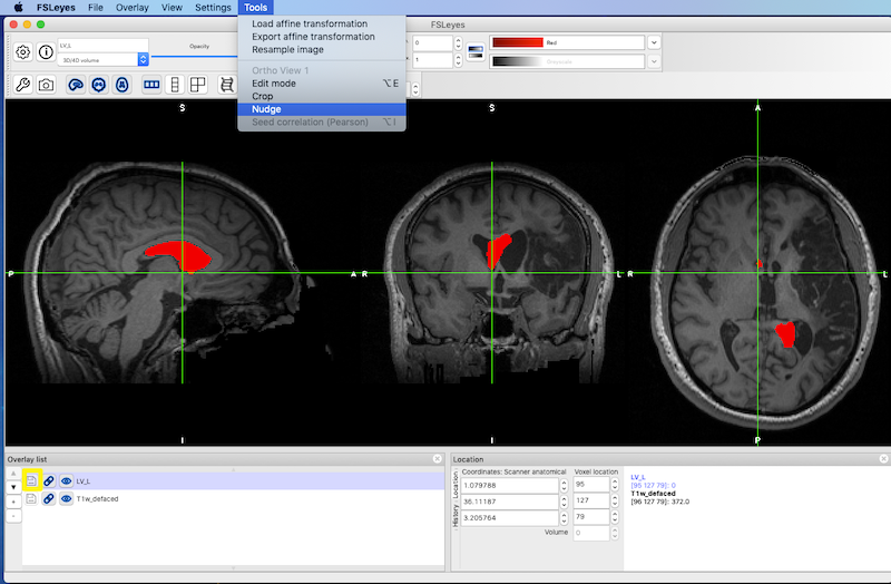
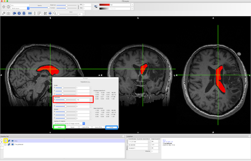
Left-Right Flip and Nudge

It can be useful to flip the normal ventricles in one hemisphere onto the abnormal ventricles in the other hemisphere to characterize ventricular enlargement. This is a two step process:

See Left-Right Flip and Nudging

Check for Hidden Problems

The section above deals with ways to clean up the way a mask looks, ensuring that it is shaped organically, like the lesion, and is not filled with simple drawing errors. However, before using a mask for image math or statistical analyses, you want to make sure that more insidious problems are not present. The checks below can prevent some of these more insidious problems for both masks and antomical images.

fslinfo and fslhd

fslinfo provides very limited information about your images. fslhd provides more. Both are useful. Try them like this:

fslinfo lesion
fslhd lesion

Ensure Zeros, not NaNs

SPM uses NaN (Not-a-Number) in addition to zeros in NIFTI images. However, some processing programs (e.g., FSL) do not handle NaN well at all. In fact fslstats will add NaN values in a mask image to the ones in that mask image, and FSLeyes will display both NaNs and ones as values distinct from zero (right-hand image below) if the range is set from -1 to 1. The bottom line is that it is a better and more robust choice for your mask images to use only zeros and ones. The following FSL command will convert all NaN values in lesion to zeros in lesion2. The resulting 1’s and 0’s in lesion2.nii.gz will be handled correctly by all viewing programs:

fslmaths lesion -nan lesion2
comparison of preferred image with zeros (left) vs image with NaNs and zeros (right)

Ensure SFORM and QFORM Match

The image header for NIFTI has two separate ways to represent positional information in a viewer. Some programs (ITK-SNAP) prefer to edit the qform and others prefer to edit the sform (SPM, FSL), but these choices have evolved over the years along with what happens to the other matrix when the preferred one gets edited (set the other to 0s, match the other to the preferred, leave the other as it was). ITK-SNAP sets the sform to 0s, a potential problem for other viewers. The following tools can help: sqdiff.sh tells you whether the sform and qform of an image differ. sqdiff_wrap.sh will run sqdiff on every image it finds in subject subdirectories (sub*) of the current directory. q2s.sh copies the qform to the sform. s2q.sh copies the sform to the qform. All are based on the fsl tool fslorient.

Note

Because the sform and qform are stored differently, they have different levels of precision. It is possible to copy the sform to the qform and still find that they are reported to be a bit different by sqdiff.sh. If you copy the qform to the sform, however, any differences will be completely removed.

If you created a lesion_mask.nii.gz in ITK-SNAP, then your header will contain a qform but not sform:

sqdiff.sh lesion

diff results for Temp lesion_mask.nii.gz:
1c1
< 0 0 0 0 0 0 0 0 0 0 0 0 0 0 0 1
---
> -0.999994 -0.00314216 0.00112513 96.8904 -0.00315573 0.99992 -0.0122661 -90.1013 0.0010865 0.0122696 0.999924 -77.9563 0 0 0 1

sqdiff.sh compares the sform and qform. You see results if they are different. In the example above, ITK-SNAP has set the sform to 0 0 0 0 0 0 0 0 0 0 0 0 0 0 0 1 which is quite different that the qform!

You can also call sqdiff_wrap.sh to get a report on all sform and qform data in sub* subdirectories of the current directory:

sqdiff_wrap.sh >> sqdiff.txt

To make the sform and qform match (a very good idea), you can run either q2s.sh or s2q.sh. After generating a mask with ITK-SNAP, you can see that the sform has been zeroed out, so we want to copy the qform to the sform:

q2s.sh lesion

Both q2s.sh and s2q.sh run on specified image file argument (as illustrated above). However, if you type the script name with no arguments, you get a choice to run on all images in the current directory or to view the help message.

Ensure Standard Orientation in NIFTI Header

Standard orientations should be Right-to-Left for sform and qform orient (e.g.)

qform_xorient Right-to-Left
qform_yorient Posterior-to-Anterior
qform_zorient Inferior-to-Superior

If you encounter an image with the following:

qform_xorient Left-to-Right
qform_yorient Posterior-to-Anterior
qform_zorient Inferior-to-Superior

then some programs will have trouble (iMango and Papaya will get the L-R wrong as of May 23, 2019). Note that this is not proper behavior for such programs, and it should be reported as a bug (it has been) Nevertheless, it doesn’t hurt to make sure everything is consistent:

See get_orient.sh to view orientations. If you have run fslreorient2std on sub-001_T1w_reoriented.nii.gz, you’ll find it is still in Left-to-Right orientation:

get_orient.sh sub-001_T1w_reoriented

See reset_orient.sh to switch the orientations and then view the results:

reset_orient.sh sub-001_T1w

Save Space on your Hard Drive

FSL has the annoying habit of saving images with a high bitdepth (32 bits). You don’t need that for structural T1w images (or T2w, or FLAIR). It justs wastes a lot of space. DWI images often use floating point values and should remaim 32 bit.

Ensure anatomical images are short (16 bit):

fslmaths anat_T1w anat_T1w -odt short

Ensure masks are binary and char (8 bit):

fslmaths lesion -bin lesion -odt char

Create a Brain Mask

It can be very useful to have a brain mask to trim the lesion if the filling algorithm leaks outside the brain. There are many ways to generate such a mask: BET in FSL , optiBET, and MRIcron.

If you are working with T1w_defaced.nii.gz, you may wish to use the native_brain_mask.nii.gz that I have generated with optiBET.

If you have normalized the head with SPM12 following our suggested approach, then you can use this standard brain mask MNI_T1_1mm_brain_mask.nii.gz. This is the 1mm MNI brain mask cropped into the space of the final SPM12 output.

If you generate your own brain mask, ensure that it has good coverage. After you have generated a lesion mask with ITK-SNAP, you should check that the lesion has not leaked outside of the brain mask (yellow arrow in figure below).

Using a brain mask to limit the spread of the lesion mask outside the brain. Yellow arrow points to lesion mask that grew outside the brain mask

You can look at the T1w image, the brain mask and the lesion mask with FSLeyes. There are several ways to start FSLeyes, but the command below shows you some of the options you can pick at the command line:

fsleyes T1w_defaced -b 70 -c 70 lesion_mask -cm Red native_brain_mask -cm Blue -a 30

This command says: Use fsleyes to view the T1w_defaced.nii.gz image. FSL looks for files with the .nii.gz suffix, so supplying that at the command line is optional. Because the image is usually too dark on my monitor, I increase the brightness -b from the default 50% to 70%. I do the same with contrast -c. Next, I want to add the lesion_mask with the red color mask -cm Red. Next, I want to add the native_brain_mask with a blue color mask -cm Blue and with alpha transparency of 30% -a 30.

You can use a command like this to trim the lesion so it only occupies the region that overlaps the brain mask, e.g.:

fslmaths lesion_mask -mul native_brain_mask -bin lesion_mask -odt char

This command says: Multiply the lesion_mask and the native_brain_mask, retaining only voxels that are in both. Then binarize the lesion mask with -bin and ensure that it doesn’t take up too much space on your drive with -odt char which sets the output datatype to 8 bits.

Note

Especially in native space, the brain mask may have inadequate coverage. This is partly because brain masking is a hard problem, and partly because brain masking is a REALLY hard problem when there is a large lesion near the surface of the brain. Scroll through the 3 orthogonal slices and think carefully about whether you want to trim the lesion with the brain mask.

Left-Right Flip Lateral Ventricle Mask

Many of the large lesions we mask are contiguous with the ventricle and result in abnormal enlargement of that ventricle. To estimate the abnormal enlargement, one can segment the normal ventricle in the other hemisphere (assume the right ventricle for this discussion) and then Left-Right flip the segmentation. In standard space, this will generally be aligned in the opposite hemisphere, but in native space, where the head is often not perfectly straight in the scanner, it may be necessary to nudge the flipped segmentation by eye. Here I describe a combination of ITK-SNAP and FSL tools and some related concerns:

As described above for lesion masking, segment and save the right lateral ventricle. Call it LV_R.nii.gz. Left-Right flip the segmentation using FSL command line tools. fslswapdim takes the mask LV_R.nii.gz as input and flips on the x axis (which is a left-right flip):

fslswapdim LV_R -x y z LV_L

Warning

The L-R flip works in isolation. That is, if you flip x only -x y z it works fine, but if you try to flip other orientations at the same time, e.g. -x -y z then x won’t flip. Weird, so keep it in mind. See Orientation Explained

In conjunction with flipping, it may be necessary to use nudge.sh (described below in Nudging), especially if you are working in native space. This is because the native space images are often tilted, so the two hemispheres may not be nicely aligned on a given slice.

Nudging

Tools like FSLeyes and MRIcron may allow you to move a mask image around relative to the anatomical underlay. But results may not carry over to image math operations or other pieces of software (Many thanks to Paul McCarthy of the FSL group for explaining this and providing an example of the right flags to provide to flirt). See the description of the problem in NIFTI Headers and Orientation and in the section on Sform and Qform.

Download and call nudge.sh to open fsleyes with the anatomical underlay and the mask you want to nudge:

nudge.sh T1w_defaced LV_L
FSLeyes: selecting the Nudge tool
  • Nudge the ventricle mask over onto the left (red box, figure below).
  • When you save the nudged mask, choose Apply (green box, figure below) and then Close (blue box, figure below).
  • Save the changes by clicking the floppy disk icon (yellow box, bottom left of figure below) and choose to overwrite the existing mask.
  • Finally, close FSLeyes. nudge.sh will apply the transformation to your mask.
FSLeyes: Using translation parameter in the nudge tool

Note

FSLeyes 0.27.3 adjusts the sform/qform matrices in the NIFTI header to project different images into a common display coordinate system. However, saving the nudged mask in FSLeyes does not currently make the image suitable for use with tools like fslmaths which require that the sform/qform of the images match (Personal Communication, 3/28/2019, Paul McCarthy). The nudge.sh script opens FSLeyes with the relevant images and then applies the necessary flirt transform to ensure that the nudged mask is ready for use with fslmaths. At some future point, FSLeyes will make the transform when you save the image, and the nudge.sh script will be irrelevant.

Rotation

Nudge allows translations and rotations. Rotations are tricky. Consider, for example, a Sylvian Fissure mask flipped from the other side of the brain. I suggest these strategies:

  1. Use the sagittal view, so you can see the relative position of the mask and the superior edge of the temporal lobe. You want your mask to sit directly above the temporal lobe and be aligned with it.
  2. When you choose Nudge from the FSLeyes Tools menu, you have 2 choices for rotation: Rotate around centre of image volume or Rotate around current cursor location. For this task, Rotate around current cursor location is the more intuitive choice. Just make sure you locate your cursor at the center of the long axis of the mask.
  3. To rock the mask in the sagittal view, rotate around the x-axis.
  4. Remember there is a reset button

Jaccard

Once you have nudged a mask, you want to make sure that it has moved in both world and voxel space. nudge.sh saves a *.back image (e.g., LV_L_back.nii.gz) which you can use to compare. Remember, looking at the images in a viewer is not enough to gaurantee the nudge has been applied. You can use this simple jaccard.sh script that tells you how much two masks overlap. In the first case, jaccard.sh warns us that the images are not in the same space and that it will compare the two masks using voxel-based orientation. It then reports that Jaccard Index is 1 (the overlap is complete) and Jaccard distance is 0 (there is no distance between the masks):

>jaccard.sh cube cubeW

WARNING:: Inconsistent orientations for individual images in pipeline!
          Will use voxel-based orientation which is probably incorrect - *PLEASE CHECK*!

Total voxels cube is 125000
Total voxels cubeW is 125000
Intersect voxels are 125000
Union voxels are 125000
Jaccard index is 1.000000
Jaccard distance is 0

In this second case, the images are in the same space (there is no warning about inconsistent voxels). In addition, the images do NOT overlap completely (Jaccard Index is less than 1; Jaccard distance is more than 0):

>jaccard.sh cube cubeW+Vox
Total voxels cube is 125000
Total voxels cubeW+Vox is 125000
Intersect voxels are 61250
Union voxels are 188750
Jaccard index is .324503
Jaccard distance is .675497

Image Math

Once you have nudged the ventricle mask into the correct location on the left, you can subtract it from the lesion mask, again, using FSL command line tools:

fslmaths lesion.nii.gz -sub LV_L.nii.gz -bin lesion_rev.nii.gz

You will need to examine the results and clean up slim isthmuses left over by the subtraction. A benefit of this approach is that you have the mask used to remove the normal ventricle, so you can always repeat the process exactly.

Several useful tools for cleaning up masks are described here: Useful Image Processing Tips and Tricks. In addition, there are details about what is stored in the NIFTI image headers and problems that can arise when working with these data, especially across multiple image processing tools.

Other

Edit Image Header (Mango)

If you encounter images with incorrect dimensions, you can revise the header using Mango Header Editing. This is handy if you have an image with the wrong slice thickness, for example.

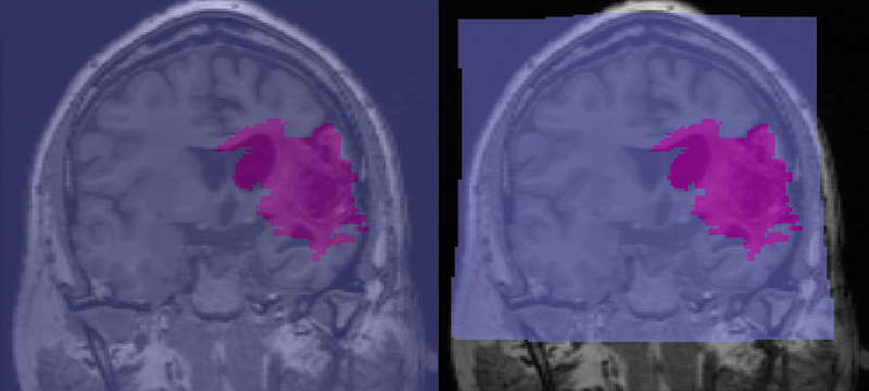
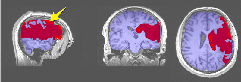
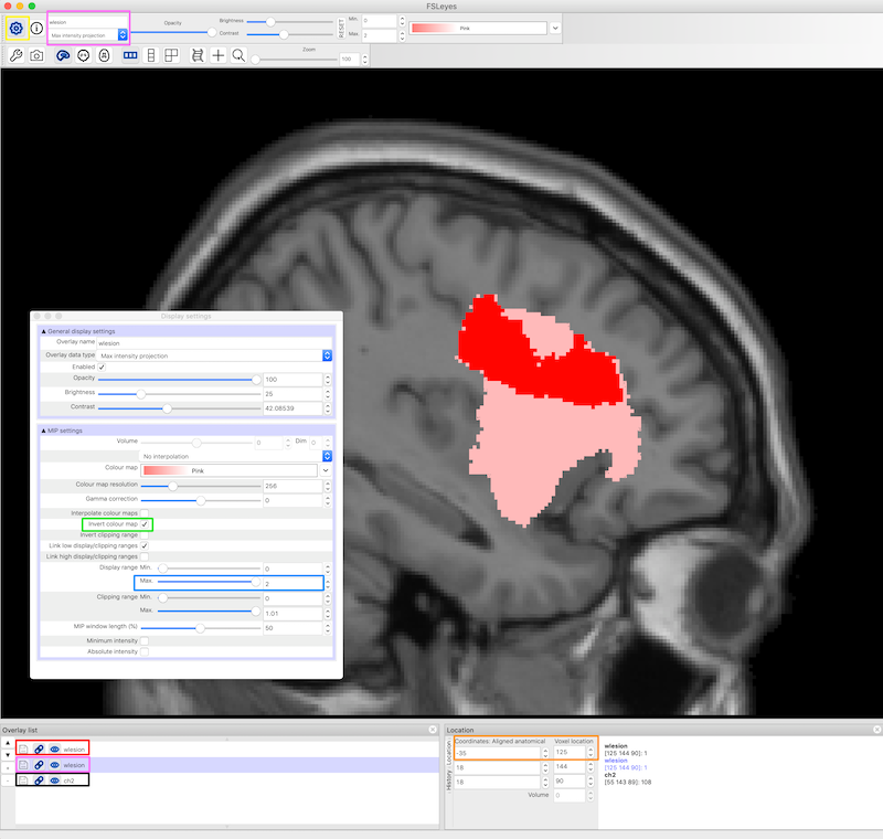
Visualization of Lesions using Maximum Intensity Projection

  1. In FSLeyes, load and display the anatomical image and two copies of the lesion file.
  2. By default the lesion file is displayed as a 3D/4D volume which displays the lesion mask for each slice. In the figure below, the 3D lesion is displayed in red (and has a red box around it in the Overlay list on the bottom left of the figure).
  3. Set the second lesion file to display as a Max Intensity Projection (MIP). It needs to be underneath the lesion file above, as it will probably be bigger. You can find the Max Intensity Projection in the upper left corner and the corresponding copy of the lesion file in the Overlay list (pink boxes, figure below). The MIP is also displayed in pink.
  4. Settings for the lesion maps are available from the gear on the upper left of FSLeyes (yellow box, figure below) and include an option to invert the colormap and otherwise refine the display. To get this particular shade of pink, we chose the pink color map, then Invert colour map (green box, figure below) and we set the Display range Max to 2. It also seems to work to use the default pink color map and set the max to about 4.
  5. We chose the ch2.nii.gz standard image, and set the x coordinates to -35 (orange box, figure below).
fsleyes interface elements for controlling multiple overlays: the lesion mask and the MIP projection of the lesion mask

Convert Images from SPM MNI to FSL MNI

Not all MNI spaces are created equal. In 1 mm resolution, the SPM MNI image is 181x217x181 but the FSL MNI image is 182x218x182. This is not a lot, but is just enough to break some tools (like Tractotron) that expect one format and not the other. Here I provide a script to convert from the SPM12 MNI format to the FSL format. This script ensures that the shape, size and datatype of the image remain exactly the same, and, in fact, the coordinates of any structures remain exactly the same. I have Mark Jenkinson from the FSL group to thank for getting all the right flirt flags. You can download spm2fsl.sh

spm2fsl.sh lesion_mask_spm_1mm