TMS
Introduction
This page describes the TMS system at the University of Arizona. This equipment belongs to the Chou lab. To request access, contact Ying-hui Chou (yinghuichou at email.arizona.edu) to discuss your proposal. The equipment resides in a locked room in the basement of the BSRL, down the hall from the MRI scanner.
- If you find inaccuracies (or typos or broken links), please let me know: dkp at email.arizona.edu. The descriptions provided below are based on extensive and excellent lab manuals prepared by Yu-chin Chen and Aneta Kielar. This page should provide you with a good sense of how you might proceed in a typical study, but it is not meant to be exhaustive. There is, for example, a 200+ page manual on the TMS-Navigator software (sorry, this is proprietary and cannot be posted).
- It might be helpful to have some kind of TMS Checklist. The linked one is in Word format so you can edit it to add or remove the details you need.
A short (3.5 minute) TMS Experience movie is available to show potential participants what it is like to get set up for TMS.
Want PDFS? Read the Docs has the ability to output documentation in other formats: pdf and epub. On the bottom left it says Read the Docs v:latest. Under Downloads, choose one of the latest options (e.g. PDF). The PDFs have much nicer formatting than if you simply “save as” pdf in your browser. The only downside is that the pdf includes everything on the website, so you’ll want to use Preview or Adobe Acrobat or something similar to extract the portion of the documentation you want. Of course, you could just print the range of pages you want as hard copies.
Hardware
To use the TMS (Transcranial Magnetic Stimulation) for research, we rely on three separate hardware systems. Here they are:
- MagPro
- Localite Computer and Camera
- MEP
MagPro
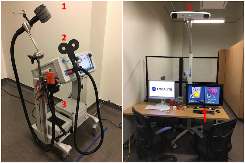
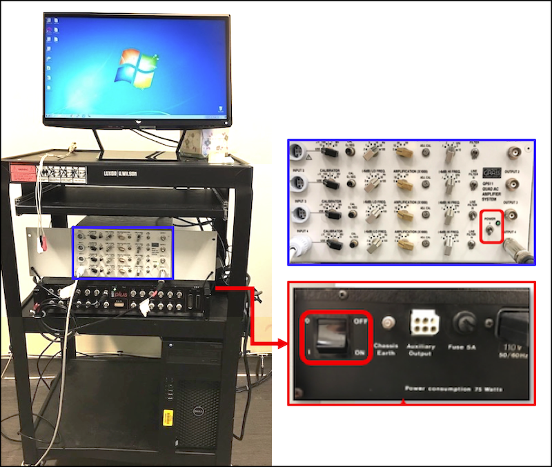
Left: The MagPro implements desired pulse sequences. The small C-B60 coil 2 administers single pulses: useful for demonstration and for identifying the resting motor threshold. The large Cool-B65 coil 1 administers pulse trains. Administering pulse trains requires the liquid cooling unit 3 and associated isolation transformer on the bottom of the MagPro cart. Right: The Localite computer runs the TMS Navigator software and the associated Polaris Spectra P7 camera 4 tracks objects using infrared and specialized reflective reference balls. The MEP computer provides Spike 2 and Pest software. The MEP monitor power is controlled by a joystick on the back middle bottom of the monitor (arrow).
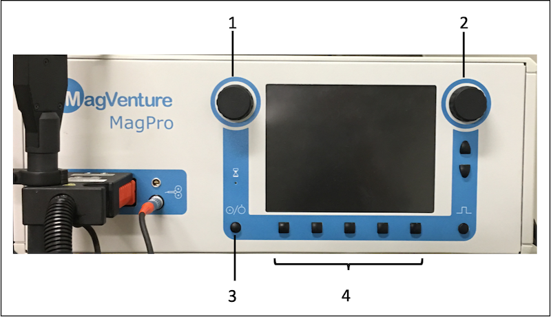
MagPro Interface: 1) Amplitude Wheel; 2) Options Wheel; 3) Enable/Disable Button; 4) Soft Keys. The function of each soft key is shown in the display just above the key. The coil plugs in on the left.
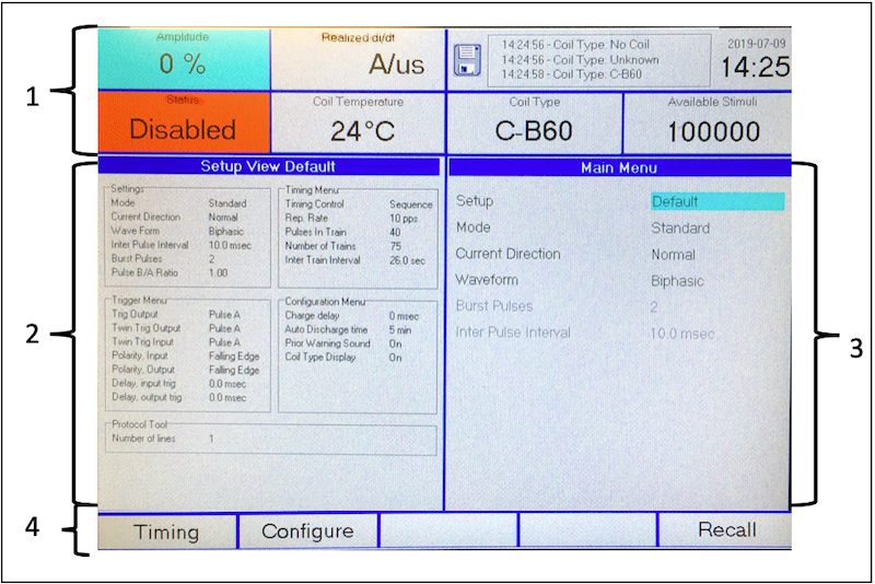
MagPro Screen: 1=status area; 2=information area; 3=selection area; 4=soft key area. This figure displays the default Main screen. 1: The amplitude wheel is one way to control the amplitude of stimulation (cyan field on the upper left). The Enable/Disable button controls the Status of the coil:  . The status area consists of fixed state fields, that do not change when you switch between Main and Timing.
 3: The pulse sequence name is displayed in the Setup field (cyan). The Options Wheel scrolls through the available pulse sequences. After finding the desired pulse sequence, press the Recall soft key. 4: The leftmost soft key switches to the timing menu if you wish to see details of the pulse sequence. Once in the timing menu, the leftmost soft key switches to say Main so you can switch back to the Main display when finished. You can see an example of the Timing display in the TBS section
Left: The C-B60 coil being attached to the MagPro; Right the same coil being detached from the MagPro.
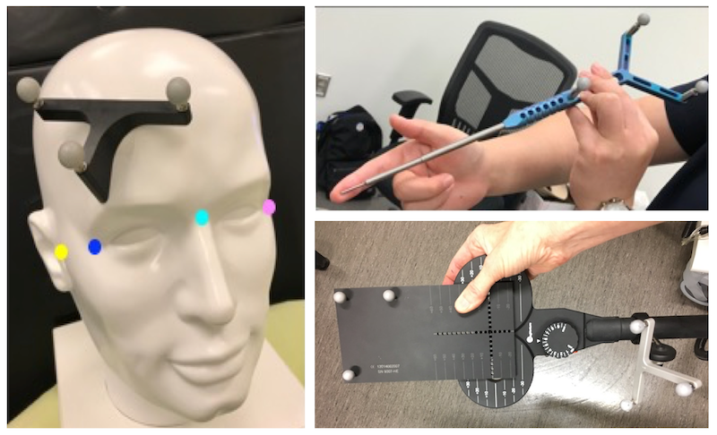
Sets of three silver reference balls are attached to the participant’s head left, the pointer upper right; the C-B60 coil and the calibration plate lower right. The three ball tracker on the participant’s head is called the reference tracker. Try not to touch or nick the reference balls to keep them clean and undamaged. The pointer is very sharp: guide the pointer with your finger, covering the tip to prevent slipping/unwanted contact.
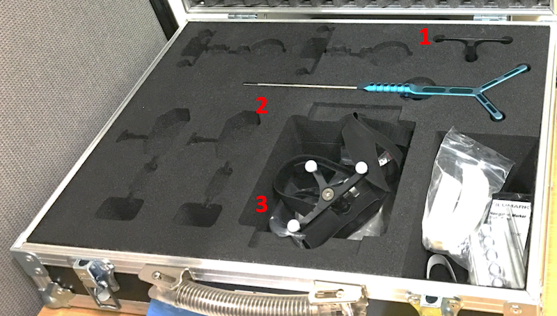
The reflector balls are stored in a clean safe padded case: The stick-on reference tracker 1; the pointer 2; and the headband reference tracker 3.
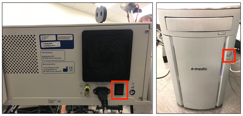
Left: Turn on the MagPro (power switch is on the back, red rectangle) and allow it to boot up completely before turning on (Right) the Localite computer (under the table; power button in red rectangle) to which it is connected. This sequence ensures the Localite computer can detect the MagPro. In addition, before using the large Cool-B65 coil, turn on the cooling unit (else the coil will remain disabled). The cooling unit on the bottom of the MagPro cart, and its power toggle is on the front.
MEP
Left: From top to bottom: The MEP (Muscle Evoked Potentials) system consists of an amplifier (white), data acquisition unit (black), and computer (black Dell) on a cart. Right: Power on white amplifier (switch on lower right) and black data acquisition unit (toggle on back of device). Generally, the MEP computer is already on, but power it on if it isn’t. The monitor, keyboard and mouse for the MEP are on the table to the right of the Localite monitor.
 TMS-Navigator Interface
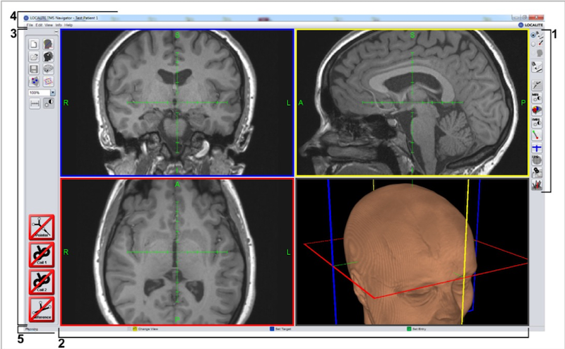
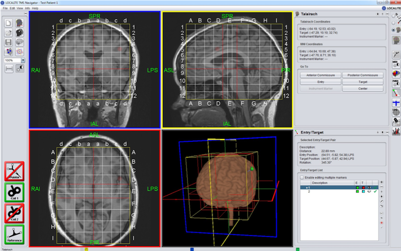
Five important areas: 1. Control area; 2. Display; 3. Toolbar; 4. Menu; 5. Status bar
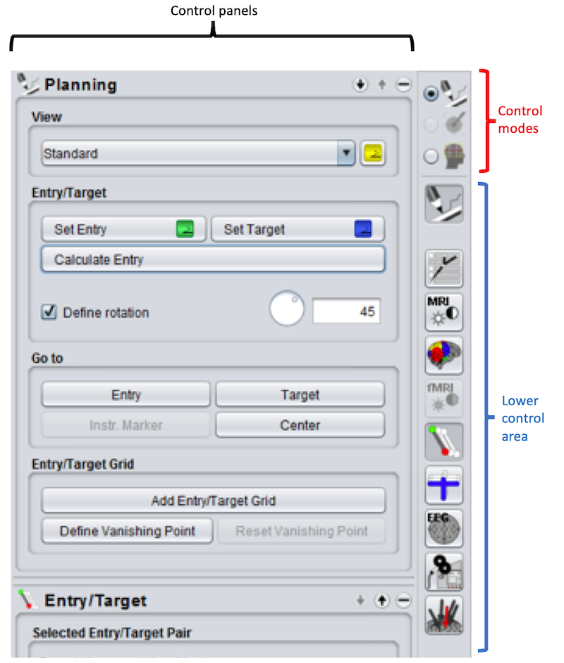
1. The Control Area is on the right of the display and divided into an upper Control Modes area and a Lower Control Area. Start with default Planning Mode (selected here). We will switch to Navigation Mode (by selecting the associated radio button) later. Clicking an icon in the Lower Control Area opens the corresponding control panel to the left of the Control Area. In this figure, we see the Planning control panel, and below that the title of the Entry/Target control panel. To the right of each control panel title are two arrows ↑ and ↓ to move the control panel up or down and a - to close the panel.
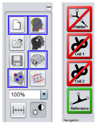
3. The Toolbar is on the left of the display area and divided into two sections illustrated above. Left: The upper section of the toolbar contains frequently used functions. We will discuss four of these functions in more detail (blue rectangles): ![]() setup session,
setup session, ![]() patient registration,
patient registration, ![]() brain segmentation and
brain segmentation and ![]() camera check. Right: The lower section of the toolbar contains four icons that indicate whether devices are being detected by the camera (Red=No; Green=Yes): Pointer; Coil1; Coil2; Reference (on the participant’s forehead).
camera check. Right: The lower section of the toolbar contains four icons that indicate whether devices are being detected by the camera (Red=No; Green=Yes): Pointer; Coil1; Coil2; Reference (on the participant’s forehead).
- The menu provides access to the Talairach definitions, MNI Planning, and lots of other things.
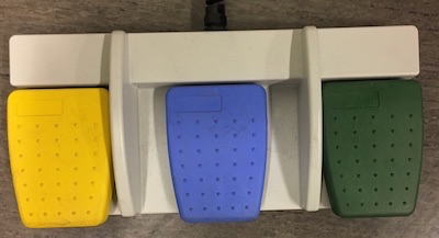
5. The Status bar along the bottom of the interface displays tiny yellow, blue and green icons that describe the footpedal functions for the active mode. These same yellow, blue and green icons appear in various control panels where they implement the same functions as the footpedals.
Once per Project: Folders and MNI Planning
Note
To create and edit MNI planning scenarios, a session does not have to be started or loaded, and the tracking system and instruments are not required.
- Create a folder on each computer (Localite and MEP) to store participant data for your lab.
- On the Localite computer, use MNI Planning to create one or more lists of stimulation targets in standard space:
- Menu: File ➜ MNI Planning ➜
+➜
- Menu: File ➜ MNI Planning ➜
- Subsequently you can load these saved targets (You can always edit this later if necessary).
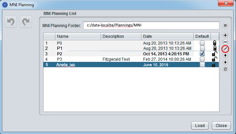
Here we are creating a new list: Aneta_lab. As soon as we click the edit button we can populate the list with our targets specified in standard space.
MNI Planning can save you a lot of time, especially if you need to identify several stimulation targets.
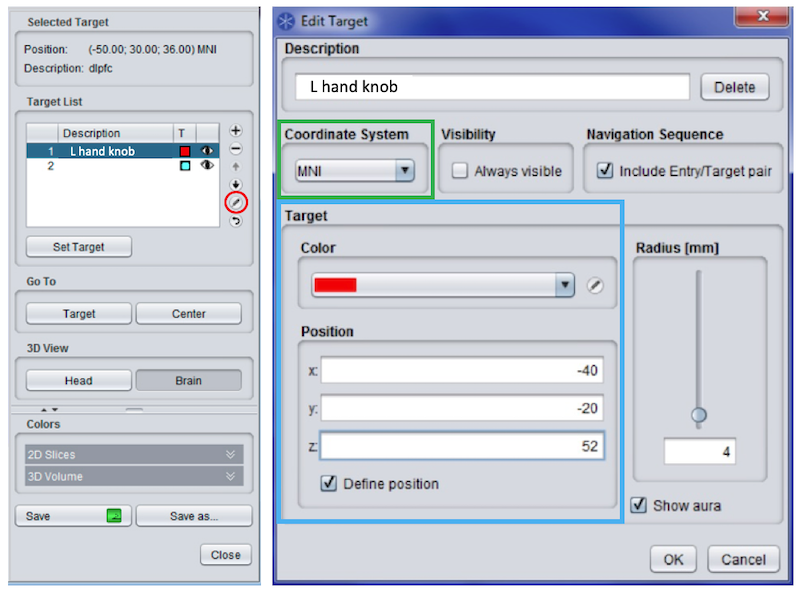
Left: After selecting the edit button for the MNI Planning list, enter a list of targets using the +. Here we define the left hand knob. You will almost always want either the left or right hand knob defined in order to test for stimulation threshold. Subsequently, edit (pencil in red circle) each target.
Right: Ensure you are using the desired coordinate system (green rectangle) before you set the target coordinates and color (blue rectangle). Press Save when you finish defining the targets in your list.
Flowcharts
Now you are somewhat familiar with the TMS hardware and the TMS Navigator software. Hopefully, you have set up MNI Planning. Now you can proceed to actually set up and run a participant. In the flowcharts below, clicking a node with a blue border will take you to the relevant section. Hardware=pink. Physical activities=cyan. Localite software=grey. MEP software=green. If order does not matter, a dotted line is used as a connector.
Before Participant Arrives
After Participant Arrives
 Spike2 Setup (MEP computer)
Click the Spike2 icon to start the program. Spike2 is used to track muscle contractions from the electrodes you will place on the participant’s hand.
New Data Document
- For each session, create a new Data Document:
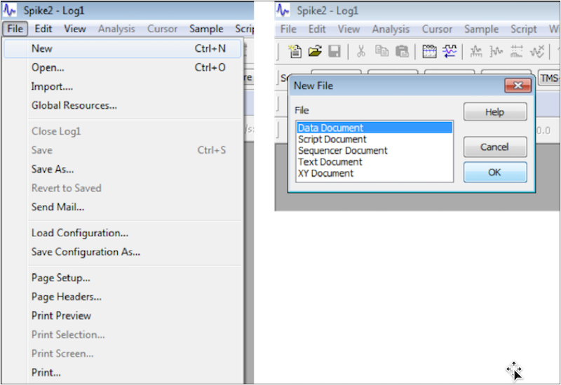
- Click the Spike2 icon on the MEP computer desktop.
- File ➜ New ➜ Data Document ➜ OK
Apply Resource File
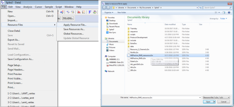
Apply the resource file: File ➜ Resource Files ➜ Apply Resource File ➜ MEPactive_RMS_resource.s2rx (in My Documents\Spike7)
TMS-EMG Configuration
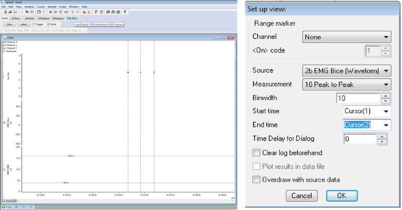
- If the script bar is not visible, then select Script ➜ Script bar from the menu
- Click View ➜ Toolbar (this shows us the Start and Stop buttons we want later)
- Press TMS-EMG on the Script bar
- Start Time: Cursor 1
- End Time: Cursor 2
- Measurement: 10 Peak to Peak
- OK
Note
Cursor 1 and Cursor 2 may not be visible after hitting okay. Don’t worry, they are present but hidden.
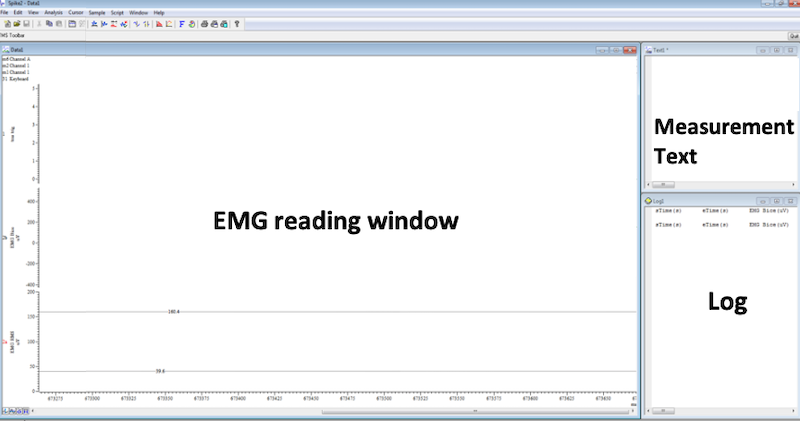
You should see three windows: the main EMG Reading Window, a Measurement Text window, and a Log.
Create a participant folder. This is where we will eventually save output from the main Spike EMG Reading window and the Log window.
 Set up Session (Localite computer, Toolbar)
- Optimally, you should have a T1-weighted scan with ~1mm isotropic voxels. You have several options for providing an anatomical scan (choose only one option, usually DICOMS):
- Bring DICOMS direct from the scanner
- Bring a Nifti volume
- If your participant is returning for additional sessions, you can load a bookmark from the planning you did last time. From the Menu, choose Load previous bookmark in New Session. This will allow you to skip ahead to participant setup. By loading the bookmark in a new session, you will have a separate folder for each session, which makes data mangement cleaner.
- If you don’t have a scan, you can use the standard MNI scan available in TMS-Navigator
- For option
1TMS Navigator looks for a folder named DICOMDIR in your Patient Folder and will show you the DICOM images within it. - For option
2, ensure that a folder containing the NIFTI anatomical file(s) is available.
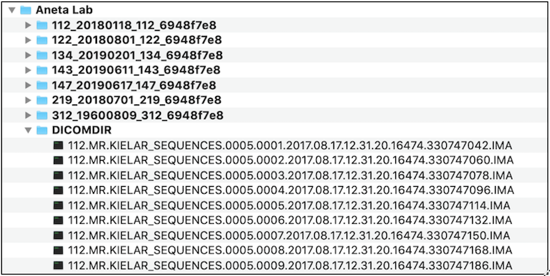
This is TMS Navigator’s preferred directory structure: The Patient Folder (called Aneta Lab here) is the folder in which you store all of your patients, not the folder for an individual patient! DICOMDIR (especially relevant if you wish to load DICOMS) is under the Patient Folder and contains all of the DICOM images. There should be no subdirectories in DICOMDIR! All of the DICOM images are at the same level.
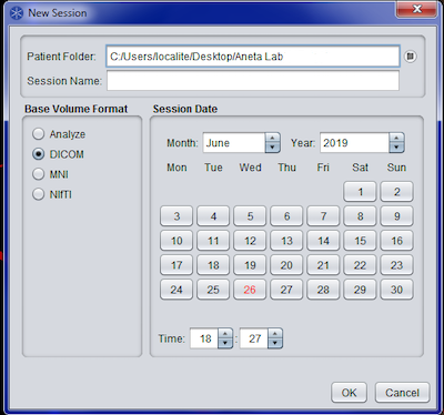
Ensure you are in the Patient Folder for your study (e.g., Aneta Lab). Select the correct Base Volume Format (left). In this figure, we chose DICOM. Provide a session name. The individual patient folder gets created in the Enter Patient Demographics step described below. At that time, the session will be correctly placed inside the individual patient folder.
Load Anatomical Image: Option 1 DICOMS
In general, you will load anatomical images directly from the scanner. This means they will be in DICOM format. TMS Navigator is specially suited to working with DICOM images.
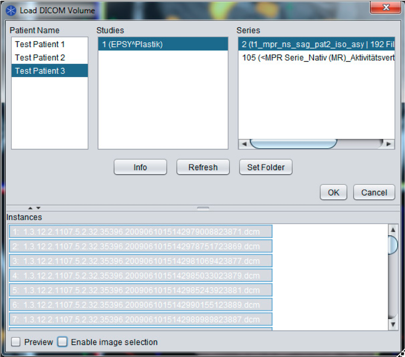
The Load DICOM Volume interface: TMS Navigator looks for the specially named folder DICOMDIR, reads the contents and parses the DICOM headers to extract information about the patients, studies and series available. You can view the images by checking Preview on the bottom left of the interface. Ensure you are in the correct folder! Do you see your patient numbers? You may need to Set Folder to point to your own DICOMDIR.
Load Anatomical Image: Option 2 NIFTI
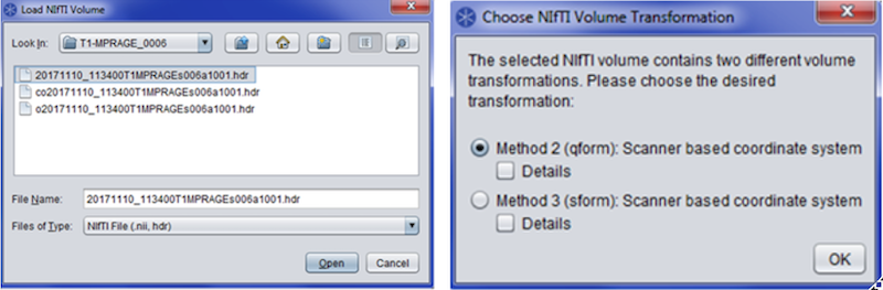
Left: If you load a NIfTI volume, you must choose the NIfTI file (*.nii or *.hdr) and open it from a location of your choosing. Right: For a Nifti file, you must specify a NIfTI Volume Transformation: Method 2 (qform) → OK. The Method (qform or sform) is specified in the TMS Navigator preferences, and is currently set to qform.
Enter Patient Demographics
Regardless of whether you loaded DICOMS or NIFTIs, you need to check that your patient demographics information is correct.
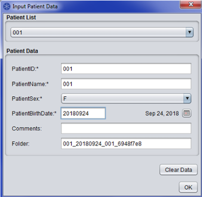
Do one of the following: 1) Select an existing patient from the Patient List (top) or 2) Enter new patient data: birthdate=today, name=ID; Sex. OK. If this is a new patient, TMS Navigator creates a folder for the individual patient based on the PatientID, PatientBirthDate, PatientName and the software’s Application Instance UID (see Folder at the bottom of the figure). The individual patient folder name gets added to PatientList.xml in the Patient Folder (e.g., Aneta Lab) and will become available in the Patient List next time. If the patient already exists, then the new session will be added to that patient’s folder.
Warning
If you do not select a patient from the patient list, TMS Navigator will create a second individual patient folder! This is true even if the patient already exists and even though the correct information is displayed in the Patient Data section! So, make sure you choose your patient from the patient list at the top (unless it is really a new patient).
Surface Threshold
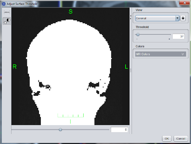
Adjust Surface Threshold (usually ~50) with the threshold slider. Check that whole brain is included in each view plane. Spots outside the head are preferable to holes in the head. Click OK. TMS Navigator needs an accurate estimation of where the surface of the head is relative to the brain inside.
 Patient Registration Landmark Setup (Toolbar)
- In addition to surface registration, specific landmarks help the software track location accurately
- Define Registration Markers (upper right in figure below): Marker List
+for each new marker: - (1) L_ear, (2) L_eye, (3) Nasion, (4) R_eye, and (5) R_ear
- Double check colors and locations.
- Cancel (Because the participant is not here to be registered).
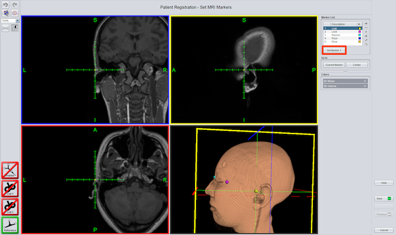
Markers and their colors have been defined in the Marker list (upper right). Each marker (colored ball) has been set to a location on the head. Moving the cursor: Either drag one of the 2D views under the cursor or double-click a tickmark on the cursor to move to that location. Here the left ear marker is selected in the list and display. The marker could be moved by selecting a different location in one of the 2D views and clicking Set Marker 1 (red rectangle).
 Brain Segmentation (Toolbar)
- Brain segmentation creates a 3D image of the brain which is useful for placing the grid correctly during Talairach definition. The brain segmentation also provides us with a nice view of the sulci and gyri of the brain which facilitates locationg targets.
- Click the cursor in the middle of a large region of WM ➜ Calculate (red rectangle).
- If the cerebellum and/or spinal cord is not included, click each and calculate again.
- Try Defaults, else Range=7-34; Sensitivity=12.
- Increased range ➜ Increased coverage
- You can reset segmentation and start over.
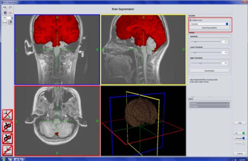
The cerebellum was not successfully segmented in this image. To include the cerebellum in the red mask, click the cerebellum and choose calculate (upper right) again.
 Brightness and Contrast (Lower Control Area)
Adjust window width (contrast) and window center:
- Reduced width (range) ➜ increased contrast
- Decreased center ➜ increased brightness
 Peel surface (Lower Control Area)
If gyri/sulci are cloudy then peel the brain surface (~3mm)
Define Talairach (Menu)
We define Talairach coordinates so that locations in the individual brain can be located in a standard coordinate system. Defining Talairach for each participant is crucial to using the MNI planning that we set up earlier.
On the menu:
- File ➜ Talairach Definition ➜ Setting markers: Comissura anterior, Comissura posterior,
- Point of Falx cerebri ➜ OK (for falx: Align with AC, Selected location defines top of brain).
- Next
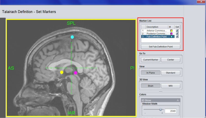
A sagittal view of the three points you need to find for talairaching: Anterior Commisure (AC) in yellow; Posterior Commisure (PC) in pink; Falx Cerebri (defines top edge of brain tissue at the midline) in cyan.
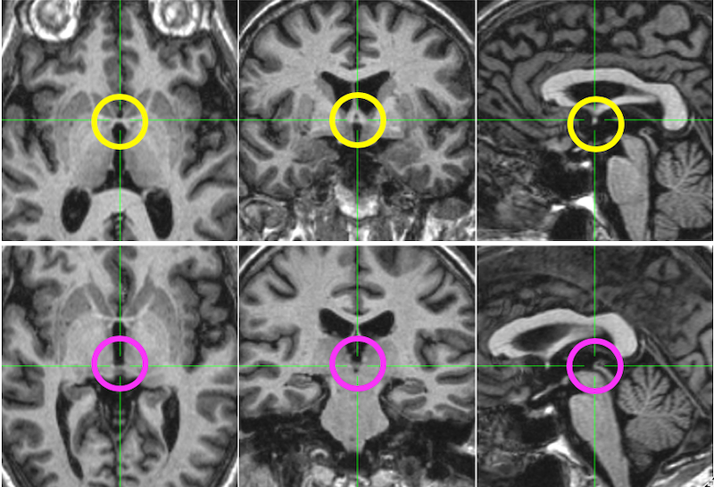
Top: The anterior commisure (AC) is displayed in the yellow circle. It is a little bridge of tissue between hemispheres. The sagittal view displays a typical cross-section of the AC. Bottom: The posterior commisure (PC) is displayed in the pink circle. It is also a little bridge of tissue between hemispheres, but it is typically more difficult to locate than the AC. You probably need multiple views to locate the PC.
Drag edges of cage to tightly encompass whole brain+cerebellum. Use 3D image to make sure no brain is outside the cage grid. OK.
Note
Although we use a simple talairaching definition to estimate standard coordinates, we can freely choose either MNI or Talairach coordinates when we plan targets. All we have to do is ensure we have explicitly selected which coordinate system we are using when we define the MNI Planning. This website can help you translate between MNI and Talairach coordinates if necessary.
Load MNI Planning Targets
Now that the participant’s brain is registered to standard space, you can load a saved MNI Planning list, e.g., File ➜ MNI Planning ➜ Kielar lab ➜ Load (Load standard space targets)
Rotation and Entry for each Target
For each target defined with MNI planning, we need to know the corresponding location for stimulation on the surface of the head.
In the lower control panel:
 Click the Entry/Target icon to view a list of your loaded targets.
 Click the Planning icon to Define Rotation and Calculate Entry. The entry is the location on the head where the coil must be applied to stimulate the desired target.
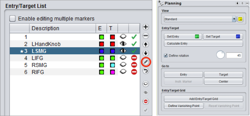
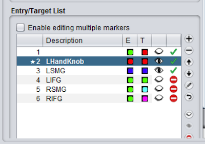
Left: E=Entry; T=Target. Click color squares to set colors (you may want the entry and target to be the same color). - removes an entry; + adds an entry. An open eye shows the Entry/Target in the display.
Right: For each target in the Entry/Target List (but see Hand Knob), set the rotation and calculate the entry.
In the Planning Control Panel:
- Check Define rotation.
- Set rotation to 45 degrees in the left hemisphere and 315 degrees in the right hemiphere.
- Click Calculate Entry in the Planning panel.
- If you have reason to set a different rotation value, you certainly should, but the above values are typical.
The Hand Knob
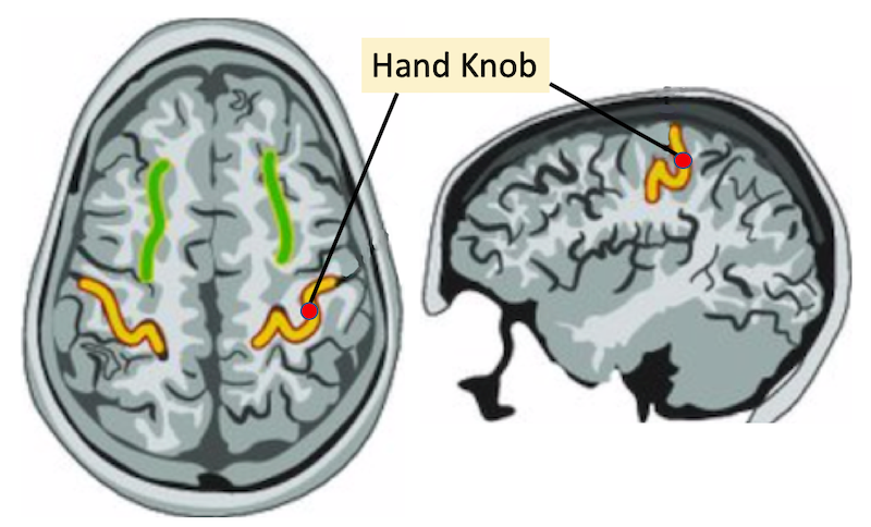
It is likely that the hand knob will not be located correctly, though it should be close. Choose the hand knob in your entry target list and then double-click the correct location on the axial display (red dot on the omicron-shaped gyrus) using the guide in the figure above. Choose Set Target and ensure that you define rotation and calculate entry in the Planning Control Panel.
Set up Participant
- Paperwork Explain the study, have the participant read and sign any consent forms, and fill out the MRI and TMS safety screening forms. Double check for contraindications!
- Provide earplugs to the participant to protect their hearing from the noise of the coil.
- Place a reference tracker on the participant’s forehead. The reference tracker is available in two forms: a stick-on version, and a headband version. In general, the stick-on reference tracker is to be preferred as it is better tolerated and more reliable. Depending on the stimulation site, you might have to use the headband (if it is not possible to place reference on forehead). If using the headband, make sure it is not too tight (can cause headaches) and not too loose (can cause the reference tracker to shift).
Electrodes
Electrodes are placed on the participant’s hand to establish the motor threshold. Choose the correct hand (e.g., the right hand if we are stimulating the left hemisphere.
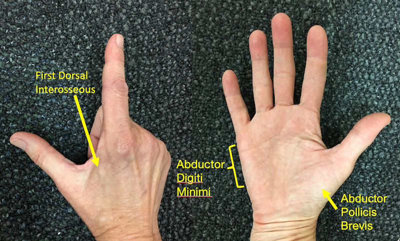
Common muscles to choose are the FDI, the ADM, and the APB;
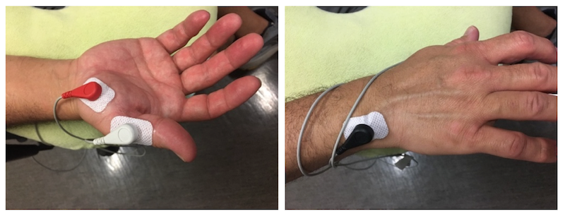
Electrode placement illustrated for the APB: Red EMG electrode ➜ thumb’s muscle belly (Abductor Pollicis Brevis); White EMG electrode ➜ thumb; Black EMG electrode ➜ back of wrist (Near Ulnar Styloid) for grounding.
Note
No matter the selected muscle, place electrodes as follows: red = muscle belly, white = tendon/bone (lateral face of selected finger), black = bony protuberance of ulnar head for grounding. Before placing the electrodes, you can ask the participant to flex the targeted muscle while palpating the muscle belly. You should feel the muscle contract (contracted muscle = firm), which will inform optimal placement of the muscle belly electrode. For the APB, illustrated here, have the participant repeatedly touch the thumb to the pinky to find the muscle belly.
- Demonstrate the pulse at lower intensity (30) on participant’s arm (as long as there is no metal in the arm) and then the head (45).
- Ask them to relax their hand.
Resume Patient Registration
Now that the participant is here and has a reference tracker affixed, we need to yoke the real world landmarks and head surface to the MRI data in TMS Navigator.
Note
The display contains four equal sized panels. To change the layout, choose View ➜ Layout in the menu. For example, you can maximize the size of panel 4 to make it easier to see the 3D representation.
Acquire Landmarks
Point to each landmark on the participant with the pointer (guide the pointer with your finger, covering the tip to prevent slipping/unwanted contact). The pointer location needs to match the landmarks on the MRI scan. For example, the specified landmark location for the left ear may vary by operator (always aim for left tragus). Ensure consistency between the marked target on the MRI scan and pointer placement. Use the 3D head image as a guide.
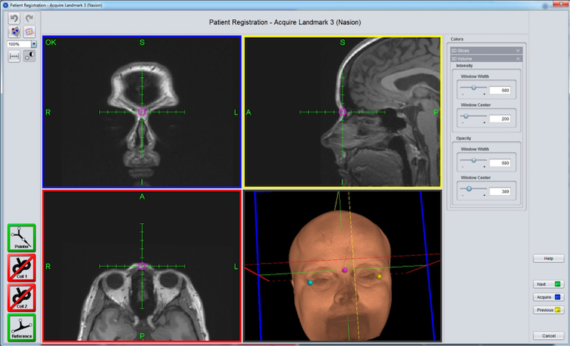
Acquiring landmarks is only successful if both the pointer and the reference (on the participant’s forehead) are visible (green) in the Lower Toolbar as illustrated here. Step on the blue footpedal to Acquire each landmark, or ask the computer operator to press the Acquire button (blue button, lower right). After acquiring all five landmarks, press the Next button (green button, lower right).

Left: TMS-Navigator evaluates the registration quality by providing a RMS deviation value (red rectangle). In this case, the RMS is 8.64, which is too high. Upper Right: Select Surface Registration to try to improve the RMS. OK. Lower Right: We are presented with a surface threshold. It is probably fine, but check it.
Surface Registration
- Place the pointer on head ➜ Blue footpedal down ➜ Drag ➜ Blue footpedal up ➜ pointer off head.
- Repeat in several directions, left & right (100-300 points).
- Get extra registration markers over the eventual stimulation site.
- Be careful not to push too hard as this can cause discomfort. You want to keep contact with skin, but just lightly tracing the pointer rather than pressing firmly.
- Click Next (green button) when you are finished adding points to recalculate the RMS.
- To accept the new RMS, click OK .
- To reject the new RMS, click Previous, Next and No. This should allow you to add more data to the surface registration.
- Hold the pointer so it is touching the head and perpendicular to it. You should see no gap between the pointer and the surface of the head (2D views).
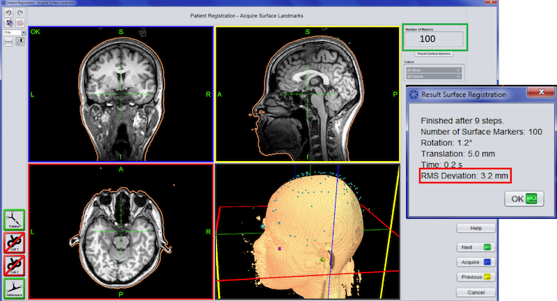
Here we have 100 points (green rectangle, upper right). We have clicked Next (green button, lower right) to recalculate the RMS. Right: Our RMS is now 3.2 mm. Click the green OK button on the Result Surface Registration window to accept.
Coil Calibration
Calibrate the coil to ensure it is recognized by the camera.
![]() Select the Instrument icon (Lower Control Area)
Select the Instrument icon (Lower Control Area)
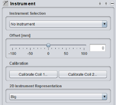
- Instrument selection ➜ Coil 1 (MagVenture C-B60)
- Place the calibration board on the coil and hold it near the participant.
- Tip the board and coil so the camera can see all the reflector balls.
- Calibrate Coil 1…
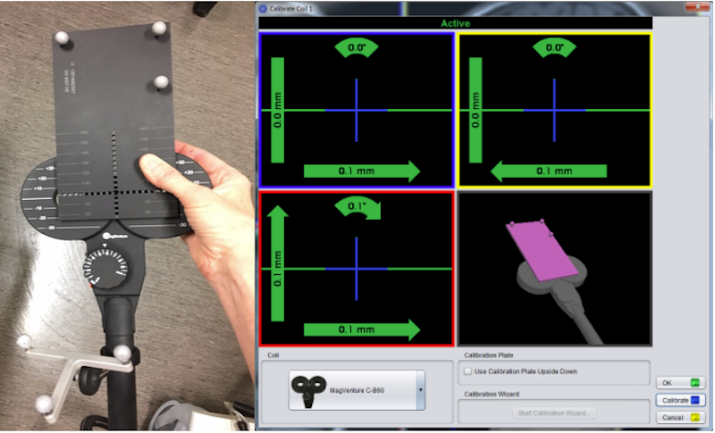
Left: C-B60 Coil with aligned calibration board. Right: When the instrument calibration displays Active in green at the top of the screen, click the blue Calibrate button, then OK. The coil is now calibrated.
 Check Camera (Polaris Spectra P7) Position (Toolbar)
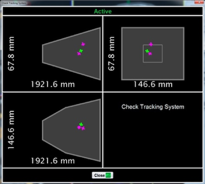
![]() If the Reference icon is red, the reflector balls on the participant’s head are not being detected, and you should check the camera position. If detected: pointer = green cross, and the reference tracker = pink cross. Coil visibility can be checked as well (pink crosses). Undetected balls are red dots.
If the Reference icon is red, the reflector balls on the participant’s head are not being detected, and you should check the camera position. If detected: pointer = green cross, and the reference tracker = pink cross. Coil visibility can be checked as well (pink crosses). Undetected balls are red dots.
Set up to Find Motor Hotspot
- We have set up the equipment and the participant. We have planned our targets and entries.
- We are going to stimulate the hand knob, and subsequently revise the location of the hand knob using an instrument marker from successful stimulation.
- We’ll need the four control panels described below.
 Switch to Navigation Mode (Upper Control Area)
 Stimulation (Lower Control Area)
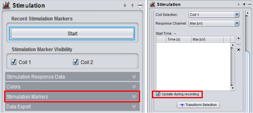
Left: The stimulation control panel. Click Start (blue rectangle) [The word Stop replaces Start on the button. We’ll use that later.] Open the Stimulation Markers dropdown (red rectangle). Right: The empty stimulation markers list is displayed. At the top, coil 1 (the small coil C-B60) should be selected. Check Update during recording (red rectangle).
Note
If you forget to choose Update during recording never fear. The stimulation markers are still being created, you just won’t see them populate the list right away. But, you should see them when you press Stop.
Choose Entry/Target (Lower Control Area)
Select the hand knob from the list.
 Set up Navigation (Lower Control Area)
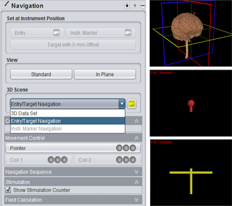
Left: The Navigation control panel showing the 3D scene dropdown. You can select from the dropdown or cycle through with the associated yellow button. Right: From top to bottom: 3D Data Set view, Entry/Target Navigation view and Instrument Marker view. Choose Entry/Target Navigation.
 Stimulator
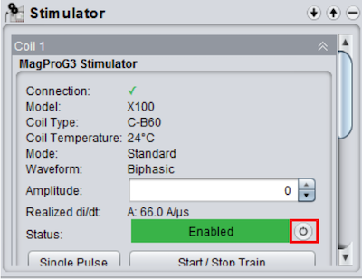
Stimulator Control Panel: This panel allows you to (1) enable a coil, (2) set the coil stimulation amplitude, and (3) start recording from the coil.
To enable a coil, change its status by clicking the button to the right (in the red box).
You can set the stimulation amplitude in the Amplitude textbox. If you use the arrows to set the stimulator amplitude, then the settings will be applied immediately. If you type an amplitude into the box, then you need to hit enter to apply the settings. You will need this when you stimulate the hand knob with various amplitude values dictated by Pest. The coil operator can trigger a pulse with the orange button on the coil.
MagPro Settings
On the MagPro screen, ensure the coil is correctly identified as the C-B60 (the small coil). Turn the Options Wheel to A. Select Recall. After selecting Recall, the details of your sequence are displayed in the information area on the left: Setup View A. You may use the Amplitude Wheel and Enable/Disable button if you prefer these to the Stimulator panel.
Warning
When you enable the coil, amplitude is reset to 0! You will need to set amplitude to 55 when you try to locate the motor hotspot. If you switch between different methods of setting the amplitude (dial on C-B60 coil, MagPro amplitude wheel and stimulator control panel), the amplitude may jump when you switch back to the previous method. Be cautious about this.
The Motor Hotspot
- Locating the motor hotspot requires TMS-Navigator on the Localite computer and Spike 2 on the MEP computer.
- Establishing the RMT additionally requires Pest on the MEP machine.
Start Sampling with Spike 2
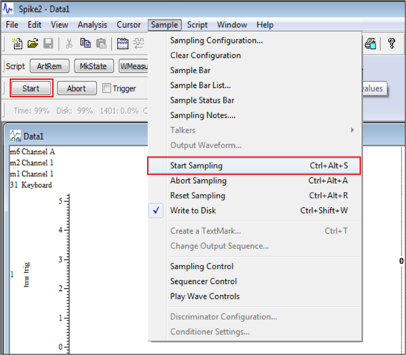
The start button is equivalent to choosing Sample ➜ Start Sampling from the menu (red rectangles).
![]() Sampling Speed is rather fast, click the slow button in the lower left corner of the Spike2 interface. About 4 clicks should do it.
Sampling Speed is rather fast, click the slow button in the lower left corner of the Spike2 interface. About 4 clicks should do it.
![]() If you go too far, there is an adjacent icon for speeding up the sampling.
If you go too far, there is an adjacent icon for speeding up the sampling.
Adjust the Y-axis (Spike 2)
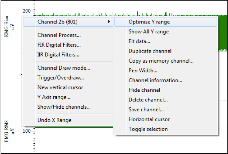
Optimize the view of the readings for both yourself and the participant. Each channel in the Spike window can have its Y-Axis adjusted: either click and drag the axis or right click the Y-Axis and select Optimize Y-Axis.
Locate the Motor Hotspot
Set the amplitude to
30. The amplitude can be set in at least 3 different ways:- Using the dial on the C-B60 coil
- Using the amplitude wheel on the Magpro
- Using the Stimulator control panel in TMS Navigator
Demonstrate the coil stimulation on the participant’s arm at amplitude=
30(as long as there is no metal in the arm), and head at amplitude=45.Set the amplitude=
55, then navigate to the handknob and stimulate it. You may have to move the coil around to find the correct spot.Watch the participant’s hand. The thumb, and not some other part of the hand, should move.
Often this is right where we placed the handknob target, but if that isn’t right, we need to move the coil around a bit and try stimulating nearby areas.
Occasionally someone has a higher threshold and you’ll need to increase the amplitude to stimulate the hotspot (e.g., we’ve seen amplitudes of 75 or even 80, but this is uncommon).
When you find a robust thumb twitch, press Stop on the stimulation control panel. We are done recording:
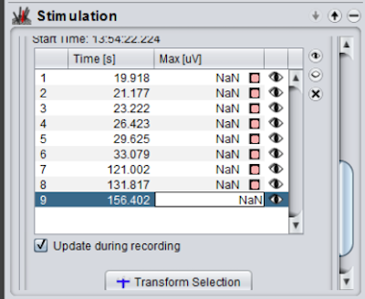
Select a stimulation from the list that corresponds to a robust thumb movement. Choose Transform Selection to open the Instrument markers Control panel and transform your selection into an instrument marker.
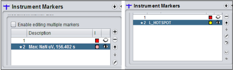
Left: The Instrument Markers Control Panel opens and displays the stimulation you chose above. Right: Give the selected marker a better name and color.
In the Navigation control panel, choose Instr. Marker Navigation to navigate using the instrument marker we just created.
 Pest
Pest
Now that we have identified the motor hotspot, start Pest. Pest is a motor threshold assessment tool. Pest runs some clever algorithms to help choose the optimal stimulation threshold. We will use Pest to stimulate the identified motor hotspot from the previous step.
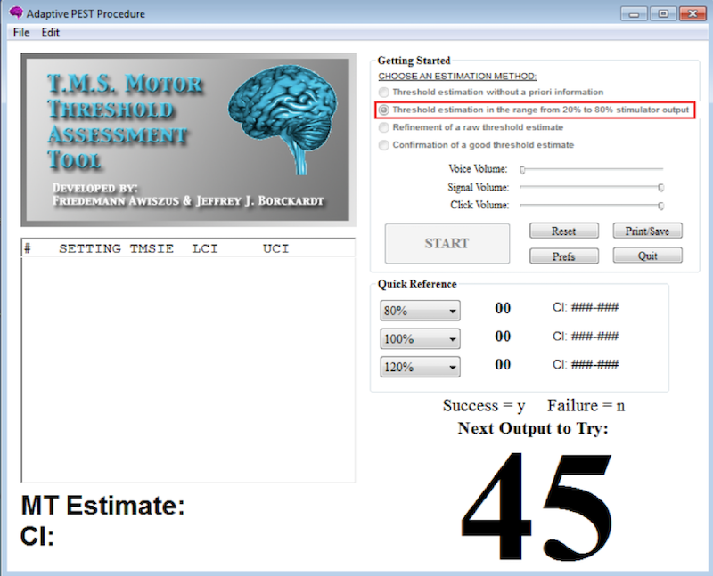
Select Threshold estimation in the range from 20% to 80% stimulator output (red rectangle) to use the default value of 45. Alternatively, it is possible to set a different threshold by selecting Refinement of raw threshold estimate, but the default is usually fine. Press START. 45 (or whatever threshold you chose) appears in the lower right as shown here. Pest will tell you what coil amplitude to try next. That amplitude can be set, for example, on the stimulator panel on the Localite machine.
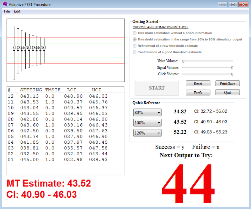
Each stimulation applied to the hand knob will either produce a finger twitch or not. If the stimulation produces a twitch, then type y into Pest. If the stimulation does NOT produce a twitch, then type n into Pest. Pest will make a sound if it detects your y or n (but it can lag a little, so make sure you wait long enough to hear the acknowleding sound). Pest will suggest the next amplitude to try. Pest displays a record of the stimulations graphically and as a table on the left. Avoid clicking the table as the software will become unresponsive (this appears to be a bug in the Windows version we are using). When Pest has sufficient data, the big number (e.g., 44 in this figure) on the lower right will turn red. This is Pest’s best guess at the motor threshold.
Test Threshold for 3/6
After identifying Pest’s guess at the motor threshold, ensure that 3/6 stimulations at that intensity produce a twitch.
- If we get too few responses, increase the threshold by
1and try again. - If we get too many responses, decrease the threshold by
1and try again. - If you get
4/6and then decrease and get2/6, then your final value is the4/6value. - After we establish the RMT we calculate 70% of that value. 70% of RMT will be our TBS intensity for both cTBS and iTBS.
Spike2: Quit and Stop (Do NOT close)

Note
When recording is stopped, it cannot be resumed. We will wait until later to save the MEP data.
- Remove electrodes from participant
- For now press the quit button (illustrated in the figure) and the stop button on the Toolbar.
- Later, when we finish the session we will save data from Spike.
- For now, you must not close Spike.
TBS (Theta Burst Stimulation)
- It is time to change the coil from the small C-B60 to the large Cool-B65 we will use for TBS. As soon as you unplug the small coil, the Localite computer will prompt you to switch or keep calibration. It does not matter what you select, or if you ignore the prompt until the large coil is plugged in.
- Ensure the cooling unit is on.
- You are going to apply either iTBS which increases cortical excitability or cTBS which decreases cortical excitability.
- Check the positioning of the coil tracker balls to ensure they won’t be in the way while you are applying the stimulation to the participant. You can move them but you should do so before you calibrate the coil.
- Calibrate the coil. This time choose Calibrate Coil 2. The calibration screen should recognize that the coil is now the Cool-B65.
- Apply the coil setup instructions to Coil 2 (the Cool-B65)
- On the MagPro screen press the Main button.
- Main will be replaced by the Timing on the bottom left of the screen.
- Turn the knob to
Yfor iTBS orCfor cTBS. Press Recall. - Press Timing to see the timing details. The
START/STOPsoftkey on the lower right is enabled. Now the pulse train can be triggered from the Stimulator panel using the Start/Stop Train button - Navigate to the target of stimulation (something other than the hand knob, we presume).
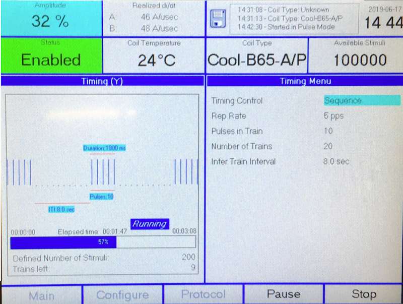
The MagPro screen with 32% amplitude, and the Cool-B65 coil enabled: The status area now reports the coil temperature and available stimuli. The Timing screen is displayed, instead of the Main screen. This is the timing for Y, the iTBS sequence. Note the long (8 sec) intertrain interval and the STOP softkey on the lower right.
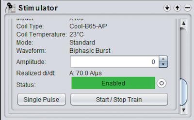
The stimulator panel with the Cool-B65 enabled: Because the Timing screen is displayed on the MagPro, the Start/Stop Train button can be used to initiate the pulse train. Of course, before initiating the pulse train, the amplitude should be set to the value you calculated earlier as 70% of the resting motor threshold.
The Cool-B65 coil is heavy which makes it difficult to hold steady for the requisite amount of time. The heavy coil may also tend to move the participant’s head as it rests against it. You may find it helpful to have the participant use the chinrest (there is a soft blue squishy disk to make it more tolerable).
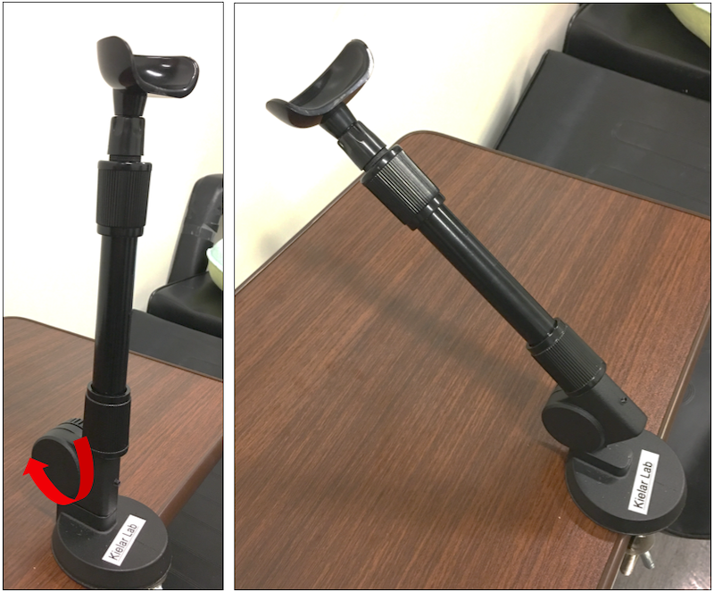
Left: In its vertical poisition the chinrest is a good height for the average participant. It can easily be extended to be taller. If the chinrest is too tall for your participant, you can tip its angle down to any height (using the adjustment marked with the red arrow). Right: The chinrest tipped at an angle.
Wrap Up the Session
- You want to save data from both the Localite and MEP machines to your external device.
- You also want to turn off hardware.
Save Data
Localite Data Save the participant folder you created earlier to your external device. MEP Data Save data from Spike2 and Pest to your external device.
- Spike2
- Save Main EMG Reading Window: Make sure that the focus is on the main EMG Reading Window and click Save in the upper left to save it to the appropriate participant folder. If the file has the *.smr extension, then you know you saved the right window.
- Save Log: Save the log by clicking in the log window and following the same steps (but the output will be a *.txt file).
- Ensure that you have named both files using your protocol and that they are in the participant folder you created.
- Copy the participant folder to your external drive.
- You can close Spike2.
- Pest
- Save the Pest data to the participant folder.
Turn off Hardware
- MEP Turn off the amplifier and data acquisition devices.
- Coil Disconnect the large coil, and reconnect the smaller coil.
- MagPro Turn off the Cooling Unit and MagPro.
- Localite Computer Turn off Localite computer.
Note
Order is not terribly important here. The MEP equipment is separate from the Coil/Localite/MagPro. It is probably best to turn off the Localite machine last (but I’m not sure why I say that).